
As the global electrical grid transitions toward renewable energy generation, the deployment of utility-scale energy storage has become an infrastructure imperative. To meet the massive capacity requirements of modern solar parks and wind farms, engineering, procurement, and construction (EPC) firms rely heavily on the Containerized BESS (Battery Energy Storage System) architecture. By packing gigawatt-hours of lithium-ion batteries into standardized 20-foot or 40-foot shipping containers, developers achieve unprecedented modularity and deployment speed.
However, this intense spatial densification creates a severe thermodynamic challenge. During high C-rate charging and discharging cycles, the internal electrochemical resistance of lithium-ion cells generates massive amounts of thermal energy. If this heat is not aggressively and uniformly dissipated, the battery cells face rapid capacity degradation, catastrophic thermal runaway, and complete system failure. Consequently, the selection of the internal Thermal Management System is no longer just a peripheral HVAC decision; it is the most critical engineering specification dictating the safety, lifespan, and financial profitability of the entire energy storage asset. This comprehensive B2B technical guide provides a rigorous engineering comparison between traditional Air Cooling and advanced Liquid Cooling technologies to determine which architecture is superior for grid-scale applications.
The Physics of Battery Heat and the Delta T (ΔT) Imperative
To evaluate a Thermal Management System, procurement directors must first understand the thermodynamic parameters of lithium-ion chemistry (specifically Lithium Iron Phosphate, or LFP, which dominates the BESS sector). LFP cells operate optimally within a very narrow temperature window, strictly between 20°C and 25°C (68°F to 77°F).
When a battery operates above this threshold, the Solid Electrolyte Interphase (SEI) layer degrades prematurely, causing irreversible capacity fade. Conversely, operating below this temperature during charging can induce lithium plating on the anode, creating microscopic dendrites that can short-circuit the cell. However, maintaining the absolute ambient temperature is only half the battle. The true measure of a high-performance Thermal Management System is its ability to minimize the temperature difference—known as Delta T (ΔT)—between any two individual cells within a massive Containerized BESS.
If the cells closest to the cooling source operate at 22°C, but the cells buried deep in the center of the rack operate at 28°C (a ΔT of 6°C), the hotter cells will age significantly faster. Because commercial battery management systems (BMS) govern the entire module based on the weakest cell, this uneven degradation will rapidly drag down the total usable capacity of the entire multi-megawatt container. According to best practices aligned with National Renewable Energy Laboratory (NREL) research, the architectural goal for utility-scale systems is to maintain a systemic ΔT of less than 3°C.
Air Cooling Architectures: The Legacy HVAC Approach
For the first decade of grid-scale energy storage, air cooling was the undisputed industry standard. Derived directly from data center and telecommunications infrastructure, air cooling relies on industrial heating, ventilation, and air conditioning (HVAC) units integrated into the walls or roof of the Containerized BESS.
Operational Mechanics of Forced Air
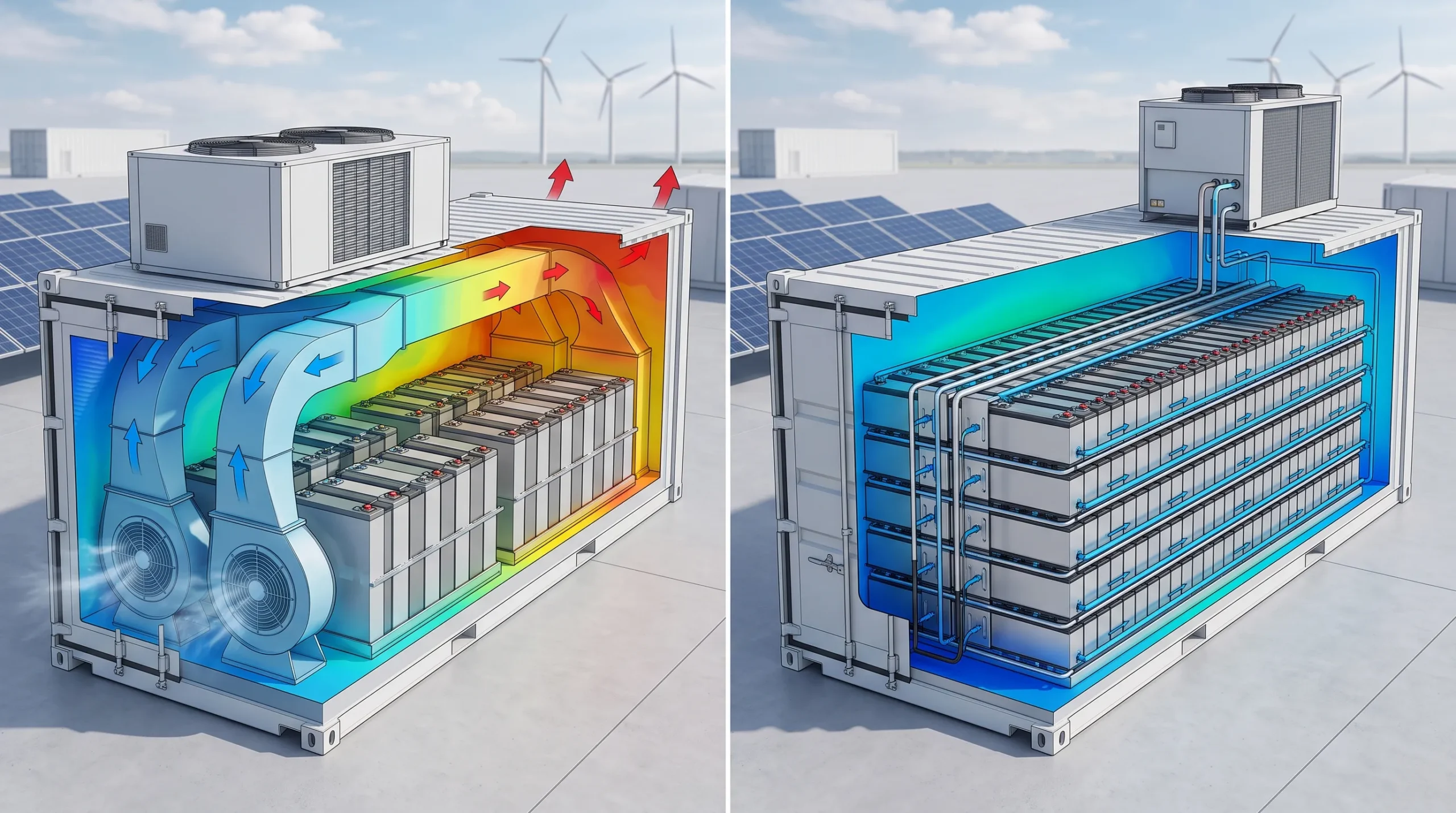
In an air-cooled system, powerful centrifugal fans force chilled air through specialized ductwork integrated into the battery racks. The cold air flows across the exterior plastic or aluminum casings of the battery modules, absorbing convective heat, and is then exhausted back to the HVAC unit to be chilled and recirculated. It is a proven, mechanically simple process that utilizes widely available commercial refrigeration components.
The Limitations of Air in High-Density Configurations
While historically reliable, air cooling is rapidly reaching its physical limitations due to the industry’s shift toward high-capacity battery cells (such as the modern 314Ah LFP format). The fundamental flaw in an air-based Thermal Management System is the inherently low specific heat capacity and poor thermal conductivity of air itself. Air simply cannot absorb heat quickly enough to cool highly dense, tightly packed battery modules.
- Severe Temperature Discrepancies: In a 40-foot container utilizing forced air, achieving a ΔT of less than 3°C is nearly impossible. The air closest to the HVAC output is freezing, but as it travels down the long battery aisle, it absorbs heat. By the time the air reaches the furthest racks, it is already warm, causing those specific modules to operate at significantly higher temperatures and degrade faster.
- Auxiliary Power Consumption: To compensate for air’s poor thermal conductivity, the HVAC fans must run at incredibly high velocities. This massive aerodynamic requirement consumes a significant portion of the stored electricity (parasitic load), thereby lowering the overall round-trip efficiency (RTE) of the Containerized BESS.
- Spatial Inefficiency: Because air requires wide physical channels to flow without extreme pressure restriction, the battery racks must be spaced further apart. This prevents EPCs from maximizing the megawatt-hour (MWh) density of the container.
Liquid Cooling Architectures: The Modern Paradigm
As the energy storage industry scales toward high-capacity 314Ah cells and gigawatt-hour deployments, relying on air to dissipate extreme thermal loads has become mathematically and financially unviable. The definitive engineering solution for high-density projects is the Liquid-Cooled Thermal Management System. This architecture completely abandons ambient convective air flow inside the battery racks, replacing it with a closed-loop fluid circuit that directly interacts with the heat source.
Operational Mechanics of Liquid Cooling
In a liquid-cooled Containerized BESS, specialized aluminum cold plates are integrated directly into the structural battery modules, maintaining constant physical contact with the cell casings. A highly efficient heat-transfer fluid—typically a 50/50 mixture of ethylene glycol and deionized water—is pumped through micro-channels within these plates. As the cells generate heat during aggressive charging or discharging, the thermal energy is instantly transferred through the conductive aluminum and absorbed by the flowing liquid. The heated coolant is then pumped out of the container to an exterior chiller unit (often roof-mounted), where the heat is expelled into the atmosphere via a condenser, and the chilled fluid is recirculated back to the batteries.
Engineering Advantages in Grid-Scale Deployments
The transition to liquid cooling unlocks several compounding advantages that directly reduce the Levelized Cost of Storage (LCOS) and maximize asset profitability:
- Superior Heat Transfer Capacity: Water-based coolants possess a specific heat capacity roughly four times greater than air, and a physical density nearly 1,000 times higher. This means the liquid loop can absorb and transport massive amounts of thermal energy away from the cells almost instantaneously, eliminating dangerous localized “hot spots.”
- Absolute Thermal Uniformity: Because the cold plates make direct contact with every single cell simultaneously, the temperature difference (ΔT) across the entire multi-megawatt Containerized BESS is easily maintained below 3°C. This strict thermal uniformity ensures synchronized cell aging, drastically extending the system’s operational lifespan (often exceeding 10,000 cycles) and preserving long-term warranty validity.
- Extreme Spatial Density: By eliminating the need for wide, aerodynamic air ducts and massive internal HVAC blower fans, engineers can pack battery modules tightly back-to-back. This spatial optimization is the exact reason why modern liquid-cooled containers can house over 5.0 MWh of energy in a standard 20-foot footprint, completely revolutionizing the land-use metrics for commercial solar parks.
- Reduced Parasitic Load: Pumping a dense, incompressible liquid through a closed loop requires significantly less mechanical energy than forcing massive volumes of air through restrictive ductwork. This reduction in auxiliary power consumption directly increases the round-trip efficiency (RTE) of the storage asset, allowing operators to dispatch more billable electricity to the grid.
Comparative Matrix: Evaluating Cooling Technologies
For B2B procurement directors, utility operators, and EPCs, selecting the correct cooling architecture requires balancing upfront Capital Expenditure (CAPEX) against long-term Operational Expenditure (OPEX) and asset degradation rates. The following matrix contrasts the critical engineering metrics of both systems.
| Engineering Metric | Traditional Air Cooling | Advanced Liquid Cooling |
|---|---|---|
| Cooling Medium Heat Capacity | Low (Requires massive volume/velocity to cool) | Maximum (Absorbs extreme heat instantly) |
| Systemic Temp Difference (ΔT) | 5°C to 8°C (High risk of uneven aging) | < 3°C (Ensures perfectly uniform cell degradation) |
| Max Energy Density (20ft Container) | Approx. 3.4 MWh to 3.7 MWh | Exceeds 5.0 MWh |
| Parasitic Power Consumption | High (Massive HVAC blower fans) | Low (Efficient fluid circulation pumps) |
| IP Rating / Dust Protection | Typically IP54 (Requires frequent filter changes) | IP65+ (Completely sealed internal environment) |
| Initial Procurement CAPEX | Lower upfront cost | 15% to 20% higher upfront premium |
Actionable Advice: When specifying a Containerized BESS for a project located in extreme climates—such as desert installations where ambient temperatures frequently exceed 45°C—procurement teams must immediately disqualify air-cooled architectures. In these environments, HVAC systems are forced to operate at maximum capacity continuously, leading to rapid compressor burnout and unacceptable parasitic power losses. Liquid cooling is the only mathematically viable option to maintain the requisite 25°C internal cell temperature without destroying the project’s overall energy yield.
Liquid Cooling Architectures: The Modern Paradigm
As the energy storage industry scales toward high-capacity 314Ah cells and gigawatt-hour deployments, relying on air to dissipate extreme thermal loads has become mathematically and financially unviable. The definitive engineering solution for high-density projects is the Liquid-Cooled Thermal Management System. This architecture completely abandons ambient convective air flow inside the battery racks, replacing it with a closed-loop fluid circuit that directly interacts with the heat source.
Operational Mechanics of Liquid Cooling
In a liquid-cooled Containerized BESS, specialized aluminum cold plates are integrated directly into the structural battery modules, maintaining constant physical contact with the cell casings. A highly efficient heat-transfer fluid—typically a 50/50 mixture of ethylene glycol and deionized water—is pumped through micro-channels within these plates. As the cells generate heat during aggressive charging or discharging, the thermal energy is instantly transferred through the conductive aluminum and absorbed by the flowing liquid. The heated coolant is then pumped out of the container to an exterior chiller unit (often roof-mounted), where the heat is expelled into the atmosphere via a condenser, and the chilled fluid is recirculated back to the batteries.
Engineering Advantages in Grid-Scale Deployments
The transition to liquid cooling unlocks several compounding advantages that directly reduce the Levelized Cost of Storage (LCOS) and maximize asset profitability:
- Superior Heat Transfer Capacity: Water-based coolants possess a specific heat capacity roughly four times greater than air, and a physical density nearly 1,000 times higher. This means the liquid loop can absorb and transport massive amounts of thermal energy away from the cells almost instantaneously, eliminating dangerous localized “hot spots.”
- Absolute Thermal Uniformity: Because the cold plates make direct contact with every single cell simultaneously, the temperature difference (ΔT) across the entire multi-megawatt Containerized BESS is easily maintained below 3°C. This strict thermal uniformity ensures synchronized cell aging, drastically extending the system’s operational lifespan (often exceeding 10,000 cycles) and preserving long-term warranty validity.
- Extreme Spatial Density: By eliminating the need for wide, aerodynamic air ducts and massive internal HVAC blower fans, engineers can pack battery modules tightly back-to-back. This spatial optimization is the exact reason why modern liquid-cooled containers can house over 5.0 MWh of energy in a standard 20-foot footprint, completely revolutionizing the land-use metrics for commercial solar parks.
- Reduced Parasitic Load: Pumping a dense, incompressible liquid through a closed loop requires significantly less mechanical energy than forcing massive volumes of air through restrictive ductwork. This reduction in auxiliary power consumption directly increases the round-trip efficiency (RTE) of the storage asset, allowing operators to dispatch more billable electricity to the grid.
Comparative Matrix: Evaluating Cooling Technologies
For B2B procurement directors, utility operators, and EPCs, selecting the correct cooling architecture requires balancing upfront Capital Expenditure (CAPEX) against long-term Operational Expenditure (OPEX) and asset degradation rates. The following matrix contrasts the critical engineering metrics of both systems.
| Engineering Metric | Traditional Air Cooling | Advanced Liquid Cooling |
|---|---|---|
| Cooling Medium Heat Capacity | Low (Requires massive volume/velocity to cool) | Maximum (Absorbs extreme heat instantly) |
| Systemic Temp Difference (ΔT) | 5°C to 8°C (High risk of uneven aging) | < 3°C (Ensures perfectly uniform cell degradation) |
| Max Energy Density (20ft Container) | Approx. 3.4 MWh to 3.7 MWh | Exceeds 5.0 MWh |
| Parasitic Power Consumption | High (Massive HVAC blower fans) | Low (Efficient fluid circulation pumps) |
| IP Rating / Dust Protection | Typically IP54 (Requires frequent filter changes) | IP65+ (Completely sealed internal environment) |
| Initial Procurement CAPEX | Lower upfront cost | 15% to 20% higher upfront premium |
Actionable Advice: When specifying a Containerized BESS for a project located in extreme climates—such as desert installations where ambient temperatures frequently exceed 45°C—procurement teams must immediately disqualify air-cooled architectures. In these environments, HVAC systems are forced to operate at maximum capacity continuously, leading to rapid compressor burnout and unacceptable parasitic power losses. Liquid cooling is the only mathematically viable option to maintain the requisite 25°C internal cell temperature without destroying the project’s overall energy yield.